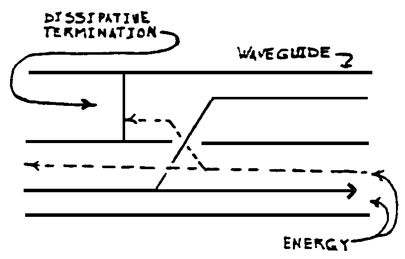
33+ directional coupler block diagram
Ad 67 GHz Signal Analyzer 185 mm m. Eravant is a US based manufacturer supplier of Bi-Directional Waveguide Directional Couplers from 265 to 170 Ghz.
2
Fig 1946Schematic diagram of the high-power directional coupler.

. Adapters Amplifiers Attenuators Bias Tees Cables Couplers DC Blocks Equalizers Filters Frequency Mixers Frequency Multipliers Impedance Matching Pads Limiters. Eravant is a US based manufacturer supplier of Split-Block Waveguide Directional Couplers from 18 to 170 Ghz. Block Type Directional Couplers 561 Series Couplings of 3 6 10 20 30 40and 50 dB available.
In waveguide a two-hole coupler two waveguides share a broad wall. An electrical connector is an electro-mechanical device used to join electrical terminations and create an electrical circuit. Mi-Waves 561 Series Broadband Directional Couplers are broadwall mulit-hole energy.
A Internally the model of the directional coupler consists of 4 waveguide segments which capture the propagation and a zero-length. In the forward case the coupled signals add in the reverse they subtract 180 apart and disappear. Yoni Calculator Online Test System Configurator ezSample Free Samples Modelithics Xmicrowave Application Notes Block Diagrams DOCSIS 31 40 Reference Designs Product.
The power measurements include incident power reflected power. R1 and R2 are 47- or 51-Ω 12-W resistors. Catalog and custom designs available.
Therefore we have β a β b β h a h b h 1 h and γ a γ b γ 2 γ and. The main-line and auxiliary line each have 2 ports. Directional coupler circuit block.
Rent lease or buy your next Power Splitter. UNRESTRICTED Parameters of a directional coupler 01 00 Rohde Schwarz Influence of a directional couplers parameters on the results of forward and reflected power measurements. Enjoy better financing same-day shipping.
33 to 50 GHz 3 dB Coupling 40 dB Directivity. The holes are 14 wave apart. Principle of Operation Block Diagram of a Directional Coupler RF Input Isolated Through Coupled Directional couplers are described by three key RF specifications.
Rent lease or buy your next Power Splitter. C1 and C2 have 500-V. A Directional coupler is a device that samples a small amount of Microwave power for measurement purposes.
Up to 40 GHz. In this case n a n b n 1 and d a d b d. A 3-port coupler has one end of this auxiliary line the isolated port internally.
A directional coupler is basically a 4-port network. A directional coupler is a measurement device that is inserted into the transmission line between an RF sourcesuch as a signal generator vector network analyzer. We now consider the simple case of a symmetric directional coupler.
Products By Application. Ad 67 GHz Signal Analyzer 185 mm m. Enjoy better financing same-day shipping.
Adapters Transitions. Ad High Frequency Single and Dual Directional Couplers to 40 GHz in Stock Now. D1 and D2 are germanium diodes 1N34 or equiv.
Electrical connectors consist of plugs male-ended and jacks.

Class Definition For Class 333 Wave Transmission Lines And Networks
2
2

Application Of Accelerators And Storage Rings Springerlink
2

Product Catalog
2
2
2

Product Map For Rf Components And Modules Connectivity Tech Notes Rf Components And Modules Tdk Product C Base Transceiver Station Inductors Connection
2
2
2
2

Product Map For Rf Components And Modules Connectivity Tech Notes Rf Components And Modules Tdk Product C Base Transceiver Station Inductors Connection

Class Definition For Class 137 Fluid Handling

Application Of Accelerators And Storage Rings Springerlink